|
|
2009 Edition Chapter 3D. Markings For Preferential Lanes
Section 3D.01 Preferential Lane Word and Symbol Markings
Support:
01 Preferential lanes are established for one or more of a wide variety of special uses, including, but not limited to, high-occupancy vehicle (HOV) lanes, ETC lanes, high-occupancy toll (HOT) lanes, bicycle lanes, bus only lanes, taxi only lanes, and light rail transit only lanes.
Standard:
02 When a lane is assigned full or part time to a particular class or classes of vehicles, the preferential lane word and symbol markings described in this Section and the preferential lane longitudinal markings described in Section 3D.02 shall be used.
03 All longitudinal pavement markings, as well as word and symbol pavement markings, associated with a preferential lane shall end where the Preferential Lane Ends (R3-12a or R3-12c) sign (see Section 2G.07) designating the downstream end of the preferential only lane restriction is installed.
04 Static or changeable message regulatory signs (see Sections 2G.03 to 2G.07) shall be used with preferential lane word or symbol markings.
05 All preferential lane word and symbol markings shall be white and shall be positioned laterally in the center of the preferential lane.
06 Where a preferential lane use exists contiguous to a general-purpose lane or is separated from a general purpose lane by a flush buffered space that can be traversed by motor vehicles, the preferential lane shall be marked with one or more of the following symbol or word markings for the preferential lane use specified:
- HOV lane—the preferential lane-use marking for high-occupancy vehicle lanes shall consist of white lines formed in a diamond shape symbol or the word message HOV. The diamond shall be at least 2.5 feet wide and 12 feet in length. The lines shall be at least 6 inches in width.
- HOT lane or ETC Account-Only lane—except as provided in Paragraph 8, the preferential lane-use marking for a HOT lane or an ETC Account-Only lane shall consist of a word marking using the name of the ETC payment system required for use of the lane, such as E-Z PASS ONLY.
- Bicycle lane—the preferential lane-use marking for a bicycle lane shall consist of a bicycle symbol or the word marking BIKE LANE (see Chapter 9C and Figures 9C-1 and 9C-3 through 9C-6).
- Bus only lane—the preferential lane-use marking for a bus only lane shall consist of the word marking BUS ONLY.
- Taxi only lane—the preferential lane-use marking for a taxi only lane shall consist of the word marking TAXI ONLY.
- Light rail transit lane—the preferential lane-use marking for a light rail transit lane shall consist of the word marking LRT ONLY.
- Other type of preferential lane—the preferential lane-use markings shall consist of a word marking appropriate to the restriction.
07 If two or more preferential lane uses are permitted in a single lane, the symbol or word marking for each preferential lane use shall be installed.
Option:
08 Preferential lane-use symbol or word markings may be omitted at toll plazas where physical conditions preclude the use of the markings (see Section 3E.01).
Guidance:
09 The spacing of the markings should be based on engineering judgment that considers the prevailing speed, block lengths, distance from intersections, and other factors that affect clear communication to the road user.
Support:
10 Markings spaced as close as 80 feet apart might be appropriate on city streets, while markings spaced as far as 1,000 feet apart might be appropriate for freeways.
Guidance:
11 In addition to a regular spacing interval, the preferential lane marking should be placed at strategic locations such as major decision points, direct exit ramp departures from the preferential lane, and along access openings to and from adjacent general-purpose lanes. At decision points, the preferential lane marking should be placed on all applicable lanes and should be visible to approaching traffic for all available departures. At direct exits from preferential lanes where extra emphasis is needed, the use of word markings (such as "EXIT" or "EXIT ONLY") in the deceleration lane for the direct exit and/or on the direct exit ramp itself just beyond the exit gore should be considered.
Option:
12 A numeral indicating the vehicle occupancy requirements established for a high-occupancy vehicle lane may be included in sequence after the diamond symbol or HOV word message.
Guidance:
13 Engineering judgment should determine the need for supplemental devices such as tubular markers, traffic cones, or other channelizing devices (see Chapter 3H).
Section 3D.02 Preferential Lane Longitudinal Markings for Motor Vehicles
Support:
01 Preferential lanes can take many forms depending on the level of usage and the design of the facility. They might be barrier-separated or buffer-separated from the adjacent general-purpose lanes, or they might be contiguous with the adjacent general-purpose lanes. Barrier-separated preferential lanes might be operated in a constant direction or be operated as reversible lanes. Some reversible preferential lanes on a divided highway might be operated counter-flow to the direction of traffic on the immediately adjacent general purpose lanes. See Section 1A.13 for definitions of terms.
02 Preferential lanes might be operated full-time (24 hours per day on all days), for extended periods of the day, part-time (restricted usage during specific hours on specified days), or on a variable basis (such as a strategy for a managed lane).
Standard:
03 Longitudinal pavement markings for preferential lanes shall be as follows (these same requirements are presented in tabular form in Table 3D-1):
- Barrier-separated, non-reversible preferential lane—the longitudinal pavement markings for preferential lanes that are physically separated from the other travel lanes by a barrier or median shall consist of a normal solid single yellow line at the left-hand edge of the travel lane(s), and a normal solid single white line at the right-hand edge of the travel lane(s) (see Drawing A in Figure 3D-1).
- Barrier-separated, reversible preferential lane—the longitudinal pavement markings for reversible preferential lanes that are physically separated from the other travel lanes by a barrier or median shall consist of a normal solid single white line at both edges of the travel lane(s) (see Drawing B in Figure 3D-1).
- Buffer-separated (left-hand side) preferential lane—the longitudinal pavement markings for a full-time or part-time preferential lane on the left-hand side of and separated from the other travel lanes by a neutral buffer space shall consist of a normal solid single yellow line at the left-hand edge of the preferential travel lane(s) and one of the following at the right-hand edge of the preferential travel lane(s):
- A wide solid double white line along both edges of the buffer space where crossing the buffer space is prohibited (see Drawing A in Figure 3D-2).
- A wide solid single white line along both edges of the buffer space where crossing the buffer space is discouraged (see Drawing B in Figure 3D-2).
- A wide broken single white line along both edges of the buffer space, or a wide broken single white lane line within the allocated buffer space (resulting in wider lanes), where crossing the buffer space is permitted (see Drawing C in Figure 3D-2).
- Buffer-separated (right-hand side) preferential lane—the longitudinal pavement markings for a full-time or part-time preferential lane on the right-hand side of and separated from the other travel lanes by a neutral buffer space shall consist of a normal solid single white line at the right-hand edge of the preferential travel lane(s) if warranted (see Section 3B.07) and one of the following at the left-hand edge of the preferential travel lane(s) (see Drawing D in Figure 3D-2):
- A wide solid double white line along both edges of the buffer space where crossing the buffer space is prohibited.
- A wide solid single white line along both edges of the buffer space where crossing of the buffer space is discouraged.
- A wide broken single white line along both edges of the buffer space, or a wide broken single white line within the allocated buffer space (resulting in wider lanes), where crossing the buffer space is permitted.
- A wide dotted single white lane line within the allocated buffer space (resulting in wider lanes) where crossing the buffer space is permitted for any vehicle to perform a right-turn maneuver.
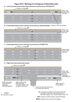
- Contiguous (left-hand side) preferential lane—the longitudinal pavement markings for a full-time or part-time preferential lane on the left-hand side of and contiguous to the other travel lanes shall consist of a normal solid single yellow line at the left-hand edge of the preferential travel lane(s) and one of the following at the right-hand edge of the preferential travel lane(s):
- A wide solid double white lane line where crossing is prohibited (see Drawing A in Figure 3D-3).
- A wide solid single white lane line where crossing is discouraged (see Drawing B in Figure 3D-3).
- A wide solid single white lane line where crossing is permitted (see Drawing C in Figure 3D-3).
- Contiguous (right-hand side) preferential lane—the longitudinal pavement markings for a full-time or part-time preferential lane on the right-hand side of and contiguous to the other travel lanes shall consist of a normal solid single white line at the right-hand edge of the preferential travel lane(s) if warranted (see Section 3B.07) and one of the following at the left-hand edge of the preferential travel lane(s) (see Drawing D in Figure 3D-3):
- A wide solid double white lane line where crossing is prohibited.
- A wide solid single white lane line where crossing is discouraged.
- A wide broken single white lane line where crossing is permitted.
- A wide dotted single white lane line where crossing is permitted for any vehicle to perform a right-turn maneuver.
| Type of Preferential Lane | Left-Hand Edge Line | Right-Hand Edge Line |
|---|---|---|
| Barrier-Separated, Non-Reversible | A normal solid single yellow line | A normal solid single white line (see Drawing A of Figure 3D-1) |
| Barrier-Separated, Reversible | A normal solid single white line | A normal solid single white line (see Drawing B of Figure 3D-1) |
| Buffer-Separated, Left-Hand Side | A normal solid single yellow line | A wide solid double white line along both edges of the buffer space where crossing is prohibited (see Drawing A of Figure 3D-2) A wide solid single white line along both edges of the buffer space where crossing is discouraged (see Drawing B of Figure 3D-2) A wide broken single white line along both edges of the buffer space, or a wide broken single white line within the buffer space (resulting in wider lanes), where crossing is permitted (see Drawing C of Figure 3D-2) |
| Buffer-Separated, Right-Hand Side | A wide solid double white line along both edges of the buffer space where crossing is prohibited (see Drawing D of Figure 3D-2) A wide solid single white line along both edges of the buffer space where crossing is discouraged (see Drawing D of Figure 3D-2) A wide broken single white line along both edges of the buffer space, or a wide broken single white line within the buffer space (resulting in wider lanes), where crossing is permitted (see Drawing D of Figure 3D-2) A wide dotted single white line within the buffer space (resulting in wider lanes) where crossing is permitted for any vehicle to perform a right-turn maneuver (see Drawing D of Figure 3D-2) |
A normal solid single white line (if warranted) |
| Contiguous, Left-Hand Side | A normal solid single yellow line | A wide solid double white line where crossing is prohibited (see Drawing A of Figure 3D-3) A wide solid single white line where crossing is discouraged (see Drawing B of Figure 3D-3) A wide broken single white line where crossing is permitted (see Drawing C of Figure 3D-3) |
| Contiguous, Right-Hand Side | A wide solid double white line where crossing is prohibited (see Drawing D of Figure 3D-3) A wide solid single white line where crossing is discouraged (see Drawing D of Figure 3D-3) A wide broken single white line where crossing is permitted (see Drawing D of Figure 3D-3) A wide dotted single white line where crossing is permitted for any vehicle to perform a right-turn maneuver (see Drawing D of Figure 3D-3) |
A normal solid single white line |
Notes:
- If there are two or more preferential lanes, the lane lines between the preferential lanes shall be normal broken white lines.
- The standard lane markings listed in this table are provided in a tabular format for reference.
- This information is also described in Paragraph 3 of Section 3D.02.
Figure 3D-1 Markings for Barrier-Separated Preferential Lanes
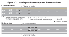
Figure 3D-2 Markings for Buffer-Separated Preferential Lanes
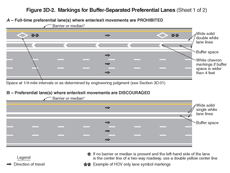
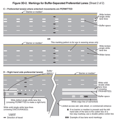
Figure 3D-3 Markings for Contiguous Preferential Lanes
Guidance:
04 Where preferential lanes and other travel lanes are separated by a buffer space wider than 4 feet and crossing the buffer space is prohibited, chevron markings (see Section 3B.24) should be placed in the buffer area (see Drawing A in Figure 3D-2). The chevron spacing should be 100 feet or greater.
Option:
05 If a full-time or part-time contiguous preferential lane is separated from the other travel lanes by a wide broken single white line (see Drawing C in Figure 3D-3), the spacing or skip pattern of the line may be reduced and the width of the line may be increased.
Standard:
06 If there are two or more preferential lanes for traffic moving in the same direction, the lane lines between the preferential lanes shall be normal broken white lines.
07 Preferential lanes for motor vehicles shall also be marked with the appropriate word or symbol pavement markings in accordance with Section 3D.01 and shall have appropriate regulatory signs in accordance with Sections 2G.03 through 2G.07.
Guidance:
08 At direct exits from a preferential lane, dotted white line markings should be used to separate the tapered or parallel deceleration lane for the direct exit (including the taper) from the adjacent continuing preferential through lane, to reduce the chance of unintended exit maneuvers.
Standard:
09 On a divided highway, a part-time counter-flow preferential lane that is contiguous to the travel lanes in the opposing direction shall be separated from the opposing direction lanes by the standard reversible lane longitudinal marking, a normal width broken double yellow line (see Section 3B.03 and Drawing A of Figure 3D-4). If a buffer space is provided between the part-time counter-flow preferential lane and the opposing direction lanes, a normal width broken double yellow line shall be placed along both edges of the buffer space (see Drawing B of Figure 3D-4). Signs (see Section 2B.26), lane-use control signals (see Chapter 4M), or both shall be used to supplement the reversible lane markings.
Figure 3D-4 Markings for Counter-Flow Preferential Lanes on Divided Highways
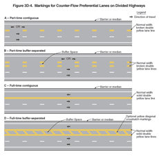
10 On a divided highway, a full-time counter-flow preferential lane that is contiguous to the travel lanes in the opposing direction shall be separated from the opposing direction lanes by a solid double yellow center line marking (see Drawing C of Figure 3D-4). If a buffer space is provided between the full-time counter-flow preferential lane and the opposing direction lanes, a normal width solid double yellow line shall be placed along both edges of the buffer space (see Drawing D of Figure 3D-4).
Option:
11 Cones, tubular markers, or other channelizing devices (see Chapter 3H) may also be used to separate the opposing lanes when a counter-flow preferential lane operation is in effect.
