Chapter 2E. Guide Signs—Freeways and Expressways
Section 2E.16 Abbreviations
Guidance:
Abbreviations should be kept to a minimum; however, they are useful
when complete destination messages produce excessively long signs.
If used, abbreviations should be unmistakably recognized by road
users (see Section 1A.14).
Periods should not be used unless a cardinal direction is abbreviated as part of a destination name.
Standard:
The words NORTH, SOUTH, EAST, and WEST shall not be abbreviated
when used with route signs to indicate cardinal directions on guide
signs.
Section 2E.17 Symbols
Standard:
Symbol designs shall be essentially like those shown in this Manual
and in the "Standard Highway Signs" book (see Section
1A.11).
Guidance:
A special effort should be made to balance legend components for
maximum legibility of the symbol with the rest of the sign.
Option:
Educational plaques may be used below symbol signs where needed.
Section 2E.18 Arrows for Interchange Guide Signs
Standard:
On all Exit Direction signs, both overhead and ground mounted, arrows
shall be upward slanting and shall be located on the side of the
sign consistent with the direction of the exiting movement.
Downward pointing arrows shall be used only for overhead guide signs to prescribe lane assignment for traffic bound for a destination or route that can be reached only by being in the designated lane(s).
Option:
Downward pointing arrows may be tilted where it is desired to emphasize
the separation of roadways.
Support:
Examples of arrows for use on guide signs are shown in Figure
2D-2. Detailed dimensions of arrows are provided in the "Standard
Highway Signs" book (see Section 1A.11).
Section 2E.19 Diagrammatic Signs
Support:
Diagrammatic signs are guide signs that show a graphic view of the
exit arrangement in relationship to the main highway. Use of such
guide signs has been shown to be superior to conventional guide
signs for some interchanges.
Standard:
Diagrammatic signs shall be designed in accordance with the following
criteria:
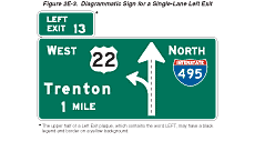
- The graphic legend shall be of a plan view showing the off-ramp arrangement (see Figure 2E-3).
- No other symbols or route shields shall be used as a substitute for arrowheads.
- They shall not be installed at the exit direction location (see Section 2E.33).
- The EXIT ONLY panel shall not be used on diagrammatic signs at any major split.
Figure 2E-3 Diagrammatic Sign for a Single-Lane Left Exit
Guidance:
Diagrammatic signs should be designed in accordance with the following
additional criteria:
- The graphic should not depict deceleration lanes.
- No more than one destination should be shown for each arrowhead, and no more than two destinations should be shown per sign.
- A black on yellow EXIT ONLY panel should be used to supplement a lane drop graphic.
- The shaft for the exit ramp movement should be shorter than, but not separated from, the through movement graphic. Where the movements are freeway splits rather than exits, the shafts should be equal in length.
- Arrow shafts should contain lane lines where appropriate.
- Route shields, cardinal directions, and destinations should be clearly related to the arrowhead, and the arrowhead should point toward the route shield for the off movement.
- The cardinal direction should be placed adjacent to the route shield, and the destination should be placed below and justified with the route shield.
Diagrammatic signs should be used at the Advance Guide sign location(s) for the following:
- Left exits (see Figure 2E-3).
- Splits where the off-route movement is to the left (see Figure 2E-4).
- Optional lane splits for non-overlapping routes (see Figure 2E-5).
- Where a two-lane exit has an optional lane that carries the through route (see Figures 2E-6 and 2E-7). These interchanges create serious expectancy problems for drivers who are unfamiliar with the interchange.
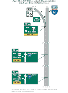
- Left exit interchange lane drop situations. In this situation, an EXIT ONLY (E11-1c) panel should be used without a down arrow for Advance Guide signs (see Figure 2E-8).
Figure 2E-4 Diagrammatic Signs for Split with Dedicated Lanes
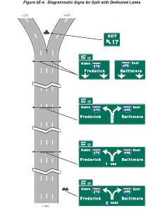
Figure 2E-5 Diagrammatic Signs for Split with Optional Lane
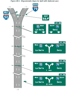
Figure 2E-6 Diagrammatic Signs for Two-Lane Exit with Optional Lane
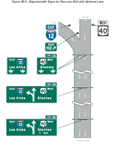
Figure 2E-7 Diagrammatic Signs for Two-Lane Exit with Optional Lane
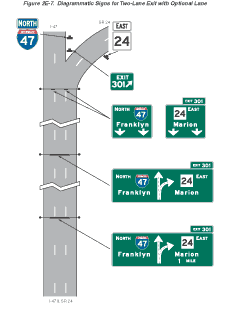
Figure 2E-8 EXIT ONLY on Left with Diagrammatic Sign for Left Lane Dropped at an Interchange
Standard:
Diagrammatic signs have been shown to be inferior to conventional
signs at cloverleaf interchanges and shall not be used at these
locations.
Support:
Specific guidelines for more detailed design of diagrammatic signs
are contained in the "Standard Highway Signs" book (see Section
1A.11).
Section 2E.20 Signing for Interchange Lane Drops
Standard:
Major guide signs for all lane drops at interchanges shall be mounted
overhead. An EXIT ONLY panel shall be used for all interchange lane
drops at which the through route is carried on the mainline.
Guidance:
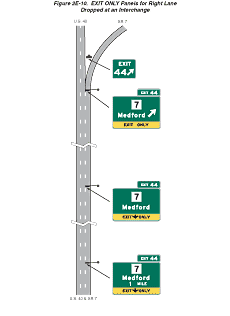
The EXIT ONLY (down arrow) (E11-1) panel (see Figure 2E-9) should
be used on all signing of lane drops on all Advance Guide signs
for right exits (see Figure 2E-10). For lane drops on the left side,
diagrammatic signing with the EXIT ONLY (E11-1c) panel (see Figure
2E-9) should be used without a down arrow for Advance Guide signs
(see Figure 2E-8).
Figure 2E-9 EXIT ONLY Panels
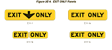
Figure 2E-10 EXIT ONLY Panels for Right Lane Dropped at an Interchange
Standard:
The Exit Direction sign (see Figure
2E-20) and E11-1a panel (see Figure 2E-9) shall be of the format
shown in Figures 2E-8 and 2E-10 for all lane drops. The standard
slanted up arrow (left or right side) shall be included on the Exit
Direction sign.
Option:
EXIT ONLY messages of either E11-1b or E11-1c formats may be used
to retrofit existing signing to warn of a lane drop situation ahead.
Standard:
If used on an existing sign, the E11-1b panel (see Figure 2E-9)
shall be placed on either side of a white down arrow. The E11-1c
panel, if used on an existing nondiagrammatic sign, shall be placed
between the lower destination message and the white down arrow.
Guidance:
Advance Guide signs for lane drops within 2 km or 1 mile of the
interchange should not contain the distance message.
Wherever the dropped lane carries the through route, diagrammatic signs should be used without the EXIT ONLY panel.
Section 2E.21 Changeable Message Signs
Standard:
Changeable message signs shall be capable of displaying several
messages in a sequence. Such messages shall be changed manually,
by remote control, or by automatic controls. Changeable message
signs shall display pertinent traffic operational and guidance information
only, not advertising.
Support:
Because technology for changeable message signs continues to advance,
a specific standard for changeable message signs is not practical.
Considerations that influence the selection of the best sign for
a particular application include conspicuity, legibility, operation,
and maintenance of the changeable message sign. This Section applies
to signs for use on freeway and expressway mainlines. It is recognized
that similar signs might be used on ramps and at ramp terminals
where smaller letter heights and the number of messages might differ
from the provisions of this Section.
Guidance:
To the extent practical, the design and application of changeable
message signs should conform to the general principles of this Manual.
Within the context of Section 2A.07,
these practices should be followed for mainline freeway and expressway
applications:
- Changeable message signs should be capital letters and have a desirable letter size of 450 mm (18 in) or a minimum letter size of 265 mm (10.6 in). Signs should be limited to not more than 3 lines with not more than 20 characters per line.
- No more than two displays should be used within any message cycle.
- Each display should convey a single thought.
- The entire message cycle should be readable at least twice by drivers traveling at the posted speed, the off-peak 85th-percentile speed, or the operating speed.
Standard:
Messages shall be centered within each line of legend. If more than
one changeable message sign is visible to road users, then only
one such sign shall display a sequential message at any given time.
A three-line changeable message sign shall be limited to not more than two messages. Techniques of message display such as fading, exploding, dissolving, or moving messages shall not be used.
Section 2E.22 Overhead Sign Installations
Support:
Specifications for the design and construction of structural supports
for highway signs have been standardized by the American Association
of State Highway and Transportation Officials (AASHTO). Overcrossing
structures can often serve for the support of overhead signs, and
might in some cases be the only practical location that will provide
adequate viewing distance. Use of these structures as sign supports
will eliminate the need for additional sign supports along the roadside.
Factors justifying the installation of overhead signs are given
in Section 2A.17. Vertical
clearance of overhead signs is discussed in Section
2A.18.
Section 2E.23 Lateral Offset
Standard:
The minimum lateral clearance outside the usable roadway shoulder
for ground-mounted freeway and expressway signs or for overhead
sign supports, either to the right or left side of the roadway,
shall be 1.8 m (6 ft). This minimum clearance shall also apply outside
of a barrier curb. If located within the clear zone, the signs shall
be mounted on crashworthy supports or shielded by appropriate crashworthy
barriers.
Guidance:
Where practical, a sign should not be less than 3 m (10 ft) from
the edge of the nearest traffic lane. Large guide signs especially
should be farther removed, preferably 9 m (30 ft) or more from the
nearest traffic lane.
Where an expressway median is 3.7 m (12 ft) or less in width, consideration should be given to spanning both roadways without a center support.
Where overhead sign supports cannot be placed a reasonably safe distance away from the line of traffic or in an otherwise protected site, they should either be designed to minimize the impact forces, or be adequately shielded by a physical barrier or guardrail of suitable design.
Standard:
Butterfly-type sign supports and other overhead noncrashworthy sign
supports shall not be installed in gores or other unprotected locations
within the clear zone.
Option:
Lesser clearances, but not generally less than 1.8 m (6 ft), may
be used on connecting roadways or ramps at interchanges.
Section 2E.24 Guide Sign Classification
Support:
Freeway and expressway guide signs are classified and treated in
the following categories:
- Route signs and Trailblazer Assemblies (see Section 2E.25);
- At-Grade Intersection signs (see Section 2E.26);
- Interchange signs (see Sections 2E.27 through 2E.36);
- Interchange Sequence signs (see Section 2E.37);
- Community Interchanges Identification signs (see Section 2E.38);
- NEXT X EXITS signs (see Section 2E.39);
- General Service signs (see Section 2E.51);
- Rest and Scenic Area signs (see Section 2E.52);
- Tourist Information and Welcome Center signs (see Section 2E.53);
- Reference Location Signs (see Section 2E.54);
- Miscellaneous guide signs (see Section 2E.55);
- Radio Information signing (see Section 2E.56);
- Carpool and Ridesharing signing (see Section 2E.57);
- Weigh Station signing (see Section 2E.58);
- Specific Service signs (see Chapter 2F); and
- Recreational and Cultural Interest Area signs (see Chapter 2H).
Section 2E.25 Route Signs and Trailblazer Assemblies
Standard:
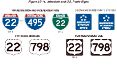
The official Route sign for the Interstate Highway System shall
be the red, white, and blue retroreflective distinctive shield adopted
by the American Association of State Highway and Transportation
Officials (see Section 2D.11).
Figure 2E-11 Interstate and U.S. Route Signs
Guidance:
Route signs (see Figure 2E-11) should be incorporated as cut-out
shields or other distinctive shapes on large directional guide signs.
Where the Interstate shield is displayed in an assembly or on the
face of a guide sign with U.S. or State Route signs, the Interstate
numeral should be at least equal in size to the numerals on the
other Route signs. The use of independent Route signs should be
limited primarily to route confirmation assemblies.
Route signs and auxiliary signs showing junctions and turns should be used for guidance on approach roads, for route confirmation just beyond entrances and exits, and for reassurance along the freeway or expressway. When used along the freeway or expressway, the Route signs should be enlarged as shown in the "Standard Highway Signs" book (see Section 1A.11). When independently mounted Route signs are used in place of Pull-Through signs, they should be located just beyond the exit.
Option:
The standard Trailblazer Assembly (see Section
2D.32) may be used on roads leading to the freeway or expressway.
Component parts of the Trailblazer Assembly may be included on a
single sign panel. Independently mounted Route signs may be used
instead of Pull-Through signs as confirmation information (see Section
2E.11). The commonly used name or trailblazer symbol for a toll
facility may be displayed on nontoll sections of the Interstate
Highway System at:
- The last exit before entering a toll section of the Interstate Highway System;
- The interchange or connection with a toll facility, whether or not the toll facility is a part of the Interstate Highway System; and
- Other locations within a reasonable approach distance of toll facilities when the name or trailblazer symbol for the toll facility would provide better guidance to road users unfamiliar with the area than would place names and route numbers.
The toll facility name or symbol may be included as a part of the guide sign installations on intersecting highways and approach roads to indicate the interchange with a toll section of an Interstate route. Where needed for the proper direction of traffic, a trailblazer for a toll facility that is part of the Interstate Highway System may be displayed with the Interstate Trailblazer Assembly.
Section 2E.26 Signs for Intersections at Grade
Guidance:
If there are intersections at grade within the limits of an expressway,
guide sign types specified in Chapter 2D
should be used. However, such signs should be of a size compatible
with the size of other signing on the expressway.
Option:
Advance Guide signs for intersections at grade may take the form
of diagrammatic layouts depicting the geometrics of the intersection
along with essential directional information.
Section 2E.27 Interchange Guide Signs
Standard:
The signs at interchanges and on their approaches shall include
Advance Guide signs and Exit Direction signs. Consistent destination
messages shall be displayed on these signs.
Guidance:
New destination information should not be introduced into the major
sign sequence for one interchange, nor should destination information
be dropped.
Reference should be made to Section 2E.10 and Sections 2E.30 through 2E.39 for a detailed description of the signs in the order that they should appear at the approach to and beyond each interchange. Guide signs placed in advance of an interchange deceleration lane should be spaced at least 245 m (800 ft) apart.
Supplemental guide signing should be used sparingly as provided in Section 2E.32.
Section 2E.28 Interchange Exit Numbering
Support:
Interchange exit numbering provides valuable orientation for the
road user on a freeway or expressway. The feasibility of numbering
interchanges or exits on an expressway will depend largely on the
extent to which grade separations are provided. Where there is appreciable
continuity of interchange facilities, interrupted only by an occasional
intersection at grade, the numbering will be helpful to the expressway
user.
Standard:
Interchange numbering shall be used in signing each freeway interchange
exit. Interchange exit numbers shall be displayed with each Advance
Guide sign, Exit Direction sign, and Gore sign. The exit number
shall be displayed on a separate plaque at the top of the Advance
Guide or Exit Direction sign. The standard exit number plaque shall
include the word EXIT, the appropriate exit number, and the suffix
letter (on multi-exit interchanges) separated from the exit number
by a space in a single-line format on a plaque 750 mm (30 in) in
height. Exit numbers shall not include the cardinal initials corresponding
to the directions of the cross route. Minimum numeral and letter
sizes are given in Tables 2E-1
through 2E-4.
If used, the interchange numbering system for expressways shall
conform to the provisions prescribed for freeways.
Option:
There are two approaches to interchange exit numbering that the
State and local highway agencies may use: (1) reference location
sign numbering or (2) consecutive numbering.
Support:
Reference location sign exit numbering is preferred over consecutive
exit numbering for two reasons: (1) if new interchanges are added
to a route, the highway agencies do not have to change the numbering
sequence; and (2) reference location sign numbering assists road
users in determining their destination distances and travel mileage.
Exit numbers may also be used with Supplemental Guide signs and Road User Service signs.
Guidance:
Exit number plaques should be located toward the top left edge of
the sign for a left exit and toward the top right edge for right
exits.
Because road users might not expect a left exit and might have difficulty in maneuvering to the left, the word LEFT should be added to the exit number plaque (see Figure 2E-3). Where a left exit is not numbered (no exit number plaque), a plaque with the word LEFT should be added to the top left edge of the sign.
Option:
The portion of the exit number plaque containing the word LEFT may
have a black legend and border on a yellow background.
Support:
The general plan for numbering interchange exits is shown in Figures
2E-12 through 2E-14.
Example exit number plaque designs are shown in Figures 2E-3 and 2E-15. Figures 2E-1, 2E-20, 2E-23, 2E-27 through 2E-32, and 2E-42 illustrate the incorporation of exit number plaques on guide signs.
Standard:
Where a route originates within a State, the southernmost or westernmost
terminus shall be the beginning point for numbering. If a loop,
spur, or circumferential route crosses State boundaries, the sequence
of numbering shall be coordinated by the States to provide continuous
numbering.
For circumferential routes, the numbering of interchanges shall be in a clockwise direction. The numbering shall begin with the first interchange west of the south end of an imaginary north-south line bisecting the circumferential route, at a radial freeway or other Interstate route, or some other conspicuous landmark in the circumferential route near a south polar location (see Figure 2E-12). The interchange numbers on loop routes shall begin at the loop interchange nearest the south or west mainline junction and increase in magnitude toward the north or east mainline junction (see Figure 2E-13). Spur route interchanges shall be numbered in ascending order starting at the interchange where the spur leaves the mainline of the principal route (see Figure 2E-13).
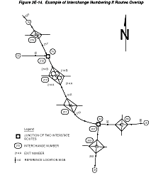
Where numbered routes overlap, continuity of interchange numbering shall be established for only one of the routes (see Figure 2E-14). If one of the routes is an Interstate, the Interstate route shall maintain continuity of interchange numbering.
Guidance:
The route chosen for continuity of interchange numbering should
also have reference location sign continuity (see Figure 2E-14).
Figure 2E-12 Example of Interchange Numbering for Mainline and Circumferential Routes
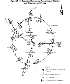
Figure 2E-13 Example of Interchange Numbering for Mainline, Loop, and Spur Routes
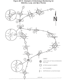
Figure 2E-14 Example of Interchange Numbering If Routes Overlap
Section 2E.29 Interchange Classification
Support:
For signing purposes, interchanges are classified as major, intermediate,
and minor. The minimum alphabet sizes contained in Tables 2E-1
and 2E-3 are
based on this classification. Descriptions of these classifications
are as follows:
- Major interchanges are subdivided into two categories: (a) interchanges with other expressways or freeways, or (b) interchanges with high-volume multi-lane highways, principal urban arterials, or major rural routes where the volume of interchanging traffic is heavy or includes many road users unfamiliar with the area.
- Intermediate interchanges are those with urban and rural routes not in the category of major or minor interchanges.
- Minor interchanges include those where traffic is local and very light, such as interchanges with land service access roads. Where the sum of exit volumes is estimated to be lower than 100 vehicles per day in the design year, the interchange is classified as minor.
Section 2E.30 Advance Guide Signs
Support:
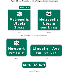
The Advance Guide sign gives notice well in advance of the exit
point of the principal destinations served by the next interchange
and the distance to that interchange (see Figure 2E-15).
Figure 2E-15 Examples of Interchange Advance Guide Signs
Guidance:
For major and intermediate interchanges (see Section
2E.29), Advance Guide signs should be placed at 1 km or 0.5
miles and at 2 km or 1 mile in advance of the exit with a third
Advance Guide sign placed at 4 km (2 mi) in advance of the exit
if spacing permits. At minor interchanges, only one Advance Guide
sign should be used. It should be located 1 to 2 km or 0.5 to 1
mile from the exit gore. If the sign is located less than 1 km or
0.5 miles from the exit, the distance shown should be to the nearest
400 m or 1/4 mile. Fractions of kilometers or decimals of kilometers
should not be used. Fractions of a mile, rather than decimals, should
be shown in all cases.
Where Advance Guide signs are provided for a left exit, diagrammatic signs should be used (see Figure 2E-3).
Standard:
When used, Advance Guide signs shall contain the distance message.
The legend on the Advance Guide signs shall be the same as the legend
on the Exit Direction sign, except that the last line shall read
EXIT X km (EXIT X MILES). If the interchange has two or more exit
roadways, the bottom line shall read EXITS X km (EXITS X MILES).
Option:
Where interchange exit numbers are used, the word EXIT may be omitted
from the bottom line. Where the distance between interchanges is
more than 2 km or 1 mile, but less than 4 km or 2 miles, the first
Advance Guide sign may be closer than 4 km or 2 miles, but not placed
so as to overlap the signing for the previous exit. Duplicate Advance
Guide signs or Interchange Sequence Series signs may be placed in
the median on the opposite side of the roadway and are not included
in the minimum requirements of interchange signing.
Guidance:
Where there is less than 245 m (800 ft) between interchanges, Interchange
Sequence Series signs should be used instead of Advance Guide signs
for the affected interchanges.
