Chapter 6H. Typical Applications
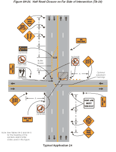
Notes for Figure 6H-24—Typical Application 24
Half Road Closure on Far Side of Intersection
Guidance:
- If the work space extends across a crosswalk, the crosswalk should be closed using the information and devices shown in Figure 6H-29.
- When turn prohibitions are implemented, two turn prohibition signs should be used, one on the near side and, space permitting, one on the far side of the intersection.
Option:
- A buffer space may be used between opposing directions of vehicular traffic as shown in this application.
- The normal procedure is to close on the near side of the intersection any lane that is not carried through the intersection. However, if there is a significant right-turning movement, then the right lane may be restricted to right turns only, as shown.
- Where the turning radius is large, a right-turn island using channelizing devices or pavement markings may be used.
- There may be insufficient space to place the back-to-back Keep Right sign and No Left Turn symbol signs at the end of the row of channelizing devices separating opposing vehicular traffic flows. In this situation, the No Left Turn symbol sign may be placed on the right and the Keep Right sign may be omitted.
- For intersection approaches reduced to a single lane, left-turning movements may be prohibited to maintain capacity for through vehicular traffic.
- Flashing warning lights and/or flags may be used to call attention to advance warning signs.
- Temporary pavement markings may be used to delineate the travel path through the intersection.
Support:
- Keeping the right lane open increases the through capacity by eliminating right turns from the open through lane.
- A temporary turn island reinforces the nature of the temporary exclusive right-turn lane and enables a second RIGHT LANE MUST TURN RIGHT sign to be placed in the island.
Figure 6H-24 Half Road Closure on Far Side of Intersection (TA-24)
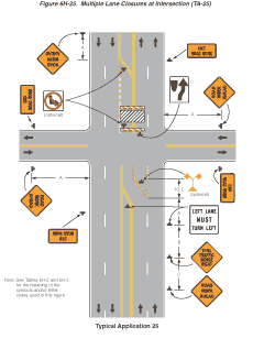
Notes for Figure 6H-25—Typical Application 25
Multiple Lane Closures at Intersection
Guidance:
- If the work space extends across a crosswalk, the crosswalk should be closed using the information and devices shown in Figure 6H-29.
- If the left through lane is closed on the near-side approach, the LEFT LANE MUST TURN LEFT sign should be placed in the median to discourage through vehicular traffic from entering the left-turn bay.
Option:
- The normal procedure is to close on the near side of the intersection any lane that is not carried through the intersection. If the left-turning movement that normally uses the closed turn bay is small and/or the gaps in opposing vehicular traffic are frequent, left turns may be permitted on that approach.
- Flashing warning lights and/or flags may be used to call attention to the advance warning signs.
Figure 6H-25 Multiple Lane Closures at Intersection (TA-25)
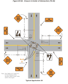
Notes for Figure 6H-26—Typical Application 26
Closure in Center of Intersection
Guidance:
- All lanes should be a minimum of 3 m (10 ft) in width as measured to the near face of the channelizing devices.
Option:
- A high-level warning device may be placed in the work space, if there is sufficient room.
- For short-term use on low-volume, low-speed roadways with vehicular traffic that does not include longer and wider heavy commercial vehicles, a minimum lane width of 2.7 m (9 ft) may be used.
- Flashing warning lights and/or flags may be used to call attention to advance warning signs.
- Unless the streets are wide, it may be physically impossible to turn left, especially for large vehicles. Left turns may be prohibited as required by geometric conditions.
- For short-duration work operations, the channelizing devices may be eliminated if a vehicle displaying high-intensity rotating, flashing, oscillating, or strobe lights is positioned in the work space.
- Vehicle hazard warning signals may be used to supplement high-intensity rotating, flashing, oscillating, or strobe lights.
Standard:
- Vehicle hazard warning signals shall not be used instead of the vehicle’s high-intensity rotating, flashing, oscillating, or strobe lights.
Figure 6H-26 Closure in Center of Intersection (TA-26)
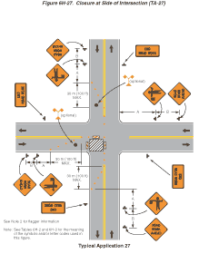
Notes for Figure 6H-27—Typical Application 27
Closure at Side of Intersection
Guidance:
- The situation depicted can be simplified by closing one or more of the intersection approaches. If this cannot be done, and/or when capacity is a problem, through vehicular traffic should be directed to other roads or streets.
- Depending on road user conditions, flagger(s) or uniformed law enforcement officer(s) should be used to direct road users within the intersection.
Standard:
- At night, flagger stations shall be illuminated, except in emergencies.
Option:
- ONE LANE ROAD AHEAD signs may also be used to provide adequate advance warning.
- Flashing warning lights and/or flags may be used to call attention to the advance warning signs.
- For short-duration work operations, the channelizing devices may be eliminated if a vehicle displaying high-intensity rotating, flashing, oscillating, or strobe lights is positioned in the work space.
- A BE PREPARED TO STOP sign may be added to the sign series.
Guidance:
- When used, the BE PREPARED TO STOP sign should be located before the Flagger symbol sign.
Support:
- Turns can be prohibited as required by vehicular traffic conditions. Unless the streets are wide, it might be physically impossible to make certain turns, especially for large vehicles.
Option:
- Vehicle hazard warning signals may be used to supplement high-intensity rotating, flashing, oscillating, or strobe lights.
Standard:
- Vehicle hazard warning signals shall not be used instead of the vehicle’s high-intensity rotating, flashing, oscillating, or strobe lights.
Figure 6H-27 Closure at Side of Intersection (TA-27)
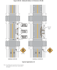
Notes for Figure 6H-28—Typical Application 28
Sidewalk Closures and Bypass Sidewalks
Standard:
- When crosswalks or other pedestrian facilities are closed or relocated, temporary facilities shall be detectable and shall include accessibility features consistent with the features present in the existing pedestrian facility.
Guidance:
- Where high speeds are anticipated, a temporary traffic barrier and, if necessary, a crash cushion should be used to separate the temporary sidewalks from vehicular traffic.
- Audible information devices should be considered where midblock closings and changed crosswalk areas cause inadequate communication to be provided to pedestrians who have visual disabilities.
Option:
- Street lighting may be considered.
- Only the TTC devices related to pedestrians are shown. Other devices, such as lane closure signing or ROAD NARROWS signs, may be used to control vehicular traffic.
- For nighttime closures, Type A Flashing warning lights may be used on barricades that support signs and close sidewalks.
- Type C Steady-Burn or Type D 360-degree Steady-Burn warning lights may be used on channelizing devices separating the temporary sidewalks from vehicular traffic flow.
- Signs, such as KEEP RIGHT (LEFT), may be placed along a temporary sidewalk to guide or direct pedestrians.
Figure 6H-28 Sidewalk Detour or Diversion (TA-28)
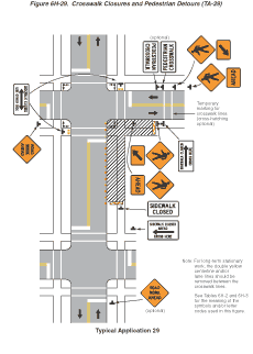
Notes for Figure 6H-29—Typical Application 29
Crosswalk Closures and Pedestrian Detours
Standard:
- When crosswalks or other pedestrian facilities are closed or relocated, temporary facilities shall be detectable and shall include accessibility features consistent with the features present in the existing pedestrian facility.
- Curb parking shall be prohibited for at least 15 m (50 ft) in advance of the midblock crosswalk.
Guidance:
- Audible information devices should be considered where midblock closings and changed crosswalk areas cause inadequate communication to be provided to pedestrians who have visual disabilities.
- Pedestrian traffic signal displays controlling closed crosswalks should be covered or deactivated.
Option:
- Street lighting may be considered.
- Only the TTC devices related to pedestrians are shown. Other devices, such as lane closure signing or ROAD NARROWS signs, may be used to control vehicular traffic.
- For nighttime closures, Type A Flashing warning lights may be used on barricades supporting signs and closing sidewalks.
- Type C Steady-Burn warning lights may be used on channelizing devices separating the work space from vehicular traffic.
- In order to maintain the systematic use of the fluorescent yellow-green background for pedestrian, bicycle, and school warning signs in a jurisdiction, the fluorescent yellow-green background for pedestrian, bicycle, and school warning signs may be used in TTC zones.
Figure 6H-29 Crosswalk Closures and Pedestrian Detours (TA-29)
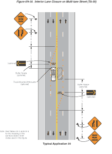
Notes for Figure 6H-30—Typical Application 30
Interior Lane Closure on Multi-lane Street
Guidance:
- This information applies to low-speed, low-volume urban streets. Where speed or volume is higher, additional signing such as LEFT LANE CLOSED XX m (FT) should be used between the signs shown.
Option:
- The closure of the adjacent interior lane in the opposing direction may not be necessary, depending upon the activity being performed and the work space needed for the operation.
- Shadow vehicles with a truck-mounted attenuator may be used.
Guidance:
- When a highway-rail grade crossing exists within or upstream of the transition area and it is anticipated that backups resulting from the lane closure might extend through the highway-rail grade crossing, the TTC zone should be extended so that the transition area precedes the highway-rail grade crossing.
- Early coordination with the railroad company should occur before work starts.
Figure 6H-30 Interior Lane Closure on Multi-lane Street (TA-30)
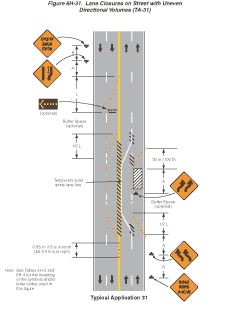
Notes for Figure 6H-31—Typical Application 31
Lane Closure on Street with Uneven Directional Volumes
Standard:
- The illustrated information shall be used only when the vehicular traffic volume indicates that two lanes of vehicular traffic shall be maintained in the direction of travel for which one lane is closed.
Option:
- The procedure may be used during a peak period of vehicular traffic and then changed to provide two lanes in the other direction for the other peak.
Guidance:
- For high speeds, a LEFT LANE CLOSED XX m (FT) sign should be added for vehicular traffic approaching the lane closure, as shown in Figure 6H-32.
- Conflicting pavement markings should be removed for long-term projects. For short-term and intermediate-term projects where this is not practical, the channelizing devices in the area where the pavement markings conflict should be placed at a maximum spacing of 0.1 S m (0.5 S ft) where S is the speed in km/h (mph). Temporary markings should be installed where needed.
- If the lane shift has curves with recommended speeds of 50 km/h (30 mph) or less, Reverse Turn signs should be used.
- Where the shifted section is long, a Reverse Curve sign should be used to show the initial shift and a second sign should be used to show the return to the normal alignment.
- If the tangent distance along the temporary diversion is less than 180 m (600 ft), the Double Reverse Curve sign should be used at the location of the first Two Lane Reverse Curve sign. The second Two Lane Reverse Curve sign should be omitted.
Option:
- A longitudinal buffer space may be used in the activity area to separate opposing vehicular traffic.
- An ALL LANES THRU supplemental plaque may be used to emphasize the point that all lanes shift and no lanes are closed.
- A work vehicle or a shadow vehicle may be equipped with a truck-mounted attenuator.
Figure 6H-31 Lane Closure on Street with Uneven Directional Volumes (TA-31)
Notes for Figure 6H-32—Typical Application 32
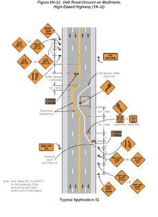
Half Road Closure on Multi-lane, High-Speed Highway
Standard:
- Pavement markings no longer applicable shall be removed or obliterated as soon as practical. Except for intermediate-term and short-term situations, temporary markings shall be provided to clearly delineate the temporary travel path. For short-term and intermediate-term situations where it is not feasible to remove and restore pavement markings, channelization shall be made dominant by using a very close device spacing.
Guidance:
- When paved shoulders having a width of 2.4 m (8 ft) or more are closed, channelizing devices should be used to close the shoulder in advance of the merging taper to direct vehicular traffic to remain within the traveled way.
- Where channelizing devices are used instead of pavement markings, the maximum spacing should be 0.1 S meters where S is the speed in km/h (0.5 S feet where S is the speed in mph).
- If the tangent distance along the temporary diversion is more than 180 m (600 ft), a Reverse Curve sign, left first, should be used instead of the Double Reverse Curve sign, and a second Reverse Curve sign, right first, should be placed in advance of the second reverse curve back to the original alignment.
Option:
- Warning lights may be used to supplement channelizing devices at night.
Guidance:
- When a highway-rail grade crossing exists within or upstream of the merging taper and it is anticipated that backups resulting from the lane closure might extend through the highway-rail grade crossing, the TTC zone should be extended so that the merging taper precedes the highway-rail grade crossing.
- When a highway-rail grade crossing exists within the activity area, provisions should be made to provide road users operating on the left side of the normal centerline with comparable warning devices as supplied for road users operating on the right side of the normal centerline.
- When a highway-rail grade crossing exists within the activity area, early coordination with the railroad company should occur before work starts.
Option:
- When a highway-rail grade crossing exists within the activity area, a flagger may be used at the highway-rail grade crossing to minimize the probability that vehicles are stopped within 4.6 m (15 ft) of the highway-rail grade crossing, measured from both sides of the outside rails.
- A truck-mounted attenuator may be used on the work vehicle and/or the shadow vehicle.
Figure 6H-32 Half Road Closure on Multilane, High-Speed Highway (TA-32)
Notes for Figure 6H-33—Typical Application 33
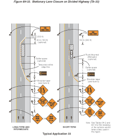
Stationary Lane Closure on Divided Highway
Standard:
- This information also shall be used when work is being performed in the lane adjacent to the median on a divided highway. In this case, the LEFT LANE CLOSED signs and the corresponding Lane Ends signs shall be substituted.
- When a side road intersects the highway within the TTC zone, additional TTC devices shall be placed as needed.
Guidance:
- When paved shoulders having a width of 2.4 m (8 ft) or more are closed, channelizing devices should be used to close the shoulder in advance of the merging taper to direct vehicular traffic to remain within the traveled way.
Option:
- A truck-mounted attenuator may be used on the work vehicle and/or shadow vehicle.
Support:
- Where conditions permit, restricting all vehicles, equipment, workers, and their activities to one side of the roadway might be advantageous.
Figure 6H-33 Stationary Lane Closure on Divided Highway (TA-33)
Notes for Figure 6H-34—Typical Application 34
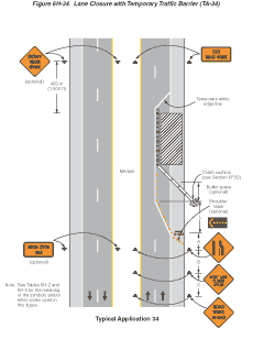
Lane Closure with Temporary Traffic Barrier
Standard:
- This information also shall be used when work is being performed in the lane adjacent to the median on a divided highway. In this case, the LEFT LANE CLOSED signs and the corresponding Lane Ends signs shall be substituted.
Guidance:
- For long-term lane closures on facilities with permanent edge lines, a temporary edge line should be installed from the start of the merging taper to the far end of the downstream taper, and conflicting pavement markings should be removed.
- The use of a barrier should be based on engineering judgment.
Standard:
- Where temporary traffic barriers are installed, the ends of the barrier shall be treated in accordance with the provisions of Section 6F.81.
- The barrier shall not be placed along the merging taper. The lane shall first be closed using channelizing devices and pavement markings.
Option:
- The barrier shown in this typical application is an example of one method that may be used to close a lane for a long-term project. If the work activity permits, a movable barrier may be used and relocated to the shoulder during nonwork periods or peak-period vehicular traffic conditions, as appropriate.
- Type C Steady-Burn warning lights may be placed on channelizing devices and the barrier parallel to the edge of pavement for nighttime lane closures.
Standard:
- If a movable barrier is used, the temporary white edge line shown in the typical application shall not be used. During the period when the right lane is opened, the sign legends and the channelization shall be changed to indicate that only the shoulder is closed, as illustrated in Figure 6H-5. The arrow panel, if used, shall be placed at the end of the shoulder taper and shall display the caution mode.
Guidance:
- If a movable barrier is used, the shift should be performed in the following manner. When closing the lane, the lane should be initially closed with channelizing devices placed along a merging taper using the same information employed for a stationary lane closure. The lane closure should then be extended with the movable-barrier transfer vehicle moving with vehicular traffic. When opening the lane, the movable-barrier transfer vehicle should travel against vehicular traffic from the termination area to the transition area. The merging taper should then be removed using the same information employed for a stationary lane closure.
Figure 6H-34 Lane Closure with Temporary Traffic Barrier (TA-34)
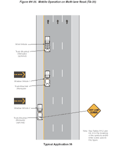
Notes for Figure 6H-35—Typical Application 35
Mobile Operation on Multi-lane Road
Standard:
- Arrow panels shall, as a minimum, be Type B, with a size of 1500 x 750 mm (60 x 30 in).
Guidance:
- Vehicles used for these operations should be made highly visible with appropriate equipment, such as: high-intensity rotating, flashing, oscillating, or strobe lights, flags, signs, or arrow panels.
- Shadow Vehicle 1 should be equipped with an arrow panel and truck-mounted attenuator.
- Shadow Vehicle 2 should be equipped with an arrow panel. An appropriate lane closure sign should be placed on Shadow Vehicle 2 so as not to obscure the arrow panel.
- Shadow Vehicle 2 should travel at a varying distance from the work operation so as to provide adequate sight distance for vehicular traffic approaching from the rear.
- The spacing between the work vehicles and the shadow vehicles, and between each shadow vehicle should be minimized to deter road users from driving in between.
- Work should normally be accomplished during off-peak hours.
- When the work vehicle occupies an interior lane (a lane other than the far right or far left) of a directional roadway having a right shoulder 3 m (10 ft) or more in width, Shadow Vehicle 2 should drive the right shoulder with a sign indicating that work is taking place in the interior lane.
Option:
- A truck-mounted attenuator may be used on Shadow Vehicle 2.
- On high-speed roadways, a third shadow vehicle (not shown) may be used with Shadow Vehicle 1 in the closed lane, Shadow Vehicle 2 straddling the edge line, and Shadow Vehicle 3 on the shoulder.
- Where adequate shoulder width is not available, Shadow Vehicle 3 may drive partially in the lane.
Figure 6H-35 Mobile Operation on Multi-lane Road (TA-35)
